




If you are looking for practical ways how to troubleshoot PCB efficiently, this field-tested engineering guide delivers structured diagnostic workflows to pinpoint and resolve the most common circuit board malfunctions fast. Many on-site technicians waste valuable time on random checks simply because they lack standardized procedures how to troubleshoot PCB properly. This guide covers visual inspections, electrical tests, fault categorization, real-world industry applications and proven repair tactics, ideal for routine maintenance, mass production quality checks and hardware project debugging.
What Preparations Should You Finish Before You Troubleshoot PCB?
Adequate pre-work significantly boosts diagnostic efficiency and prevents irreversible secondary damage to finished circuit boards. Always verify testing tools, working surroundings and basic power safety rules prior to starting any fault inspection process.
Essential Testing Instruments
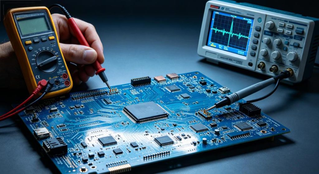
- Digital multimeter: Measures continuity, resistance, operating voltage and basic passive component parameters
- Portable oscilloscope: Captures abnormal signal waveforms to analyze errors within high-frequency circuit sections
- Isopropyl alcohol and soft cleaning tools: Eliminates surface dust, leftover flux residues and other surface contaminants
Core Safety Operating Guidelines
Disconnect all external power sources fully before opening up any circuit assembly to avoid electric hazards.
Perform proper static discharge procedures to protect delicate sensitive integrated chips mounted on the board.
How to Carry Out Visual Inspection to Spot Visible PCB Defects?
Visual examination serves as the most time-efficient preliminary screening method. Most exterior physical faults can be confirmed without relying on any electronic measuring devices. Focus closely on component appearances and overall board surface conditions during observation.
Check Abnormal Physical States of Electronic Components
Check electrolytic capacitors for bulged tops or visible electrolyte leakage marks.
Examine power resistors, inductors and power semiconductor parts for black burn traces and discoloration.
Inspect Overall Surface Condition of Printed Circuit Boards
Check exposed copper tracks for cracks, peeling issues and severe oxidative corrosion.
Examine all soldered joints to identify cold solder joints, empty solder points and unintended solder bridges.
How to Use a Multimeter to Troubleshoot PCB Power Circuit Malfunctions?
Power supply related failures rank among the most frequent issues on functional PCB units. Targeted voltage reading and continuity tests help technicians quickly confirm whether power distribution loops run normally or suffer from hidden short-circuit issues.
Common Power Circuit Fault Diagnosis Reference Table
| Fault Manifestation | Core Detection Approach | Primary Root Cause |
| No stable output voltage | Test input end voltage and fuse on-off status | Blown safety fuse or internal open circuit inside power loops |
| Fluctuating working voltage | Test filter capacitor performance and actual circuit load | Degraded energy storage components or unstable load connection status |
| Instant shutdown right after power-up | Measure conduction status between power lines and ground lines | Accidental solder bridging or internally damaged semiconductor parts |
| Excessive surface temperature during operation | Detect actual working current of each separate branch circuit | Local circuit overload and unexpected current surge phenomenon |
How to Locate Open Circuits and Short Circuits on PCB Conductive Tracks?
Disconnected tracks and concealed short-circuit points directly lead to total or partial functional failure of electronic circuits. Technicians can adopt multimeter continuity and resistance modes to complete rapid fault positioning without full component disassembly.
Switch the multimeter to buzzer continuity mode to judge the connection status of linked tracks swiftly.
For hidden short circuits inside multilayer boards, adopt segmented power supply separation to narrow down fault ranges step by step.
Avoid excessive grinding on solder mask layers when repairing broken thin copper conductive tracks.
How to Identify and Replace Damaged Active Components on PCB?
Core active electronic parts including transistors, diodes and integrated circuits are prone to failure under sudden current surges or prolonged high-temperature working environments. Simple online and offline testing methods can accurately judge the working condition of such components.
Fast Testing Methods for Diodes and Transistors
Utilize the multimeter diode test mode to check forward and reverse conduction characteristics so as to confirm internal breakdown damage.
Confirm accurate pin definitions first to prevent misjudgment caused by incorrect testing positions.
Practical Judgment Tips for Common IC Failures
Compare actual measured pin voltage values with standard reference data listed in official component datasheets.
If all peripheral supporting circuits work normally yet core functions fail, prioritize replacing the main control integrated circuit.
How to Resolve Poor Contact and Intermittent Solder Joint Failures?
Intermittent poor contact faults are notoriously tricky during daily maintenance work. Purpose-built vibration tests and temperature variation tests can effectively reproduce such unstable hidden faults for accurate confirmation.
Gently shake external connecting wires and plug-in modules to check for sudden functional changes.
Apply mild thermal treatment on suspected solder joints to verify the existence of incomplete soldering issues.
Clean oxidized metal contact pins thoroughly to restore stable physical connection performance.
Core Industrial Scenarios That Require Regular PCB Troubleshooting
Different operating environments trigger distinct types of circuit board faults. Familiarizing yourself with industry-specific common failure rules can drastically cut down actual on-site troubleshooting time.
Automotive Electronics Industry
Vehicle-mounted control PCB often develops loose solder joints resulting from long-term continuous vibration.
Regular scheduled troubleshooting effectively prevents sudden breakdowns of in-vehicle electronic control systems during driving operations.
Industrial Automation Industry
Main control board PCB used inside factory automated equipment easily suffers reduced insulation performance due to accumulated dust and humid ambient air.
Timely routine fault checks guarantee uninterrupted stable operation of automated production assembly lines.
Consumer Electronics Industry
Ultra-thin PCB adopted in portable smart electronic devices is susceptible to track fractures caused by frequent bending and external extrusion.
Basic daily troubleshooting practices help extend the overall service lifespan of mainstream consumer electronic products.
Power Electronics Industry
High-power drive PCB accumulates massive working heat, which greatly accelerates the aging speed of built-in electronic components.
Periodic professional troubleshooting effectively minimizes unexpected production halts triggered by power circuit failures.
How to Perform Zoned Troubleshooting on Complex Multilayer PCB?
Internal hidden faults existing inside multilayer printed circuit boards cannot be observed directly from external appearances. Technicians can apply partition power supply control and segmented signal tracing methods to lock exact fault areas in a logical sequence.
Divide the complete circuit board into independent power supply zones, signal transmission zones and core control zones for separate inspection.
Disconnect unnecessary peripheral auxiliary circuits in advance to rule out external signal interference factors.
Refer to official multilayer stackup layout documents to avoid blind detection targeting inner-layer conductive lines.
Practical Measures to Prevent Recurring PCB Faults
Successful fault repair is not the ultimate solution. Implementing targeted protective and optimizing measures can effectively stop identical or similar malfunctions from recurring in long-term practical application.
Carry out batch replacement of aging components once mass identical faults are discovered within the same product batch.
Apply conformal coating protective layers on PCB units deployed in highly humid and dust-intensive working environments.
Optimize external power supply matching designs to lower impact risks brought by instantaneous voltage surges.
How to Tell Apart Inherent Design Defects and User-Caused PCB Damages?
Repeatedly occurring PCB abnormal conditions do not always stem from improper later-stage usage; many issues originate from unreasonable structural designs formed in the early research and development phase. Clear classification helps solve core problems fundamentally.
If multiple circuit boards from the same production batch show identical faults, such issues mostly belong to inherent design loopholes.
Single independent board damage is usually linked to irregular manual operation or harsh external environmental impacts.
Sort out collected fault data and feed back optimization suggestions to upgrade subsequent new-generation circuit board designs.
FAQ: Frequently Asked Questions About How to Troubleshoot PCB
This question-and-answer section gathers high-frequency doubts raised during routine PCB fault diagnosis work, delivering concise, practical and field-verified solutions based on abundant real maintenance experience.
Do I need to remove all electronic components when I troubleshoot PCB?
There is no such necessity. Most common circuit faults can be located accurately through online voltage measurement and continuity tests. Only suspected faulty components need to be detached for independent performance verification to save overall working hours.
Why does a PCB work normally occasionally yet malfunction randomly?
Such intermittent failures are mainly caused by incomplete soldering, unstable physical contact or component thermal drift. Technicians can adopt heating and cooling contrast testing methods to quickly reproduce faults and confirm exact problematic positions.
Is maintenance feasible for severely burnt and damaged PCB?
Once the base board substrate gets carbonized or internal multilayer structures suffer permanent damage, such circuit boards cannot be fully restored for stable usage. Only boards with surface track damage or single independent component burnout are suitable for professional repair and reuse.
Which type of PCB fault poses the greatest challenge during troubleshooting?
Concealed inner-layer short circuits and subtle high-frequency signal interference faults are the most difficult to diagnose accurately. Resolving such issues requires combined usage of multiple testing instruments plus in-depth circuit principle analysis.
Will long-term high working temperature induce new PCB faults easily?
Definitely yes. Continuous over-temperature operation speeds up component aging progress and weakens the firmness of all soldered joints. Reasonable heat dissipation structural design and regular operating temperature monitoring can effectively lower overall failure rates.
Professional PCB Manufacturing and Custom Technical Support Services
After mastering full sets of systematic methods how to troubleshoot PCB, you are fully capable of handling daily circuit board maintenance tasks, production line quality inspections and various equipment fault debugging jobs efficiently. Adopting standardized diagnostic workflows can cut down overall maintenance expenses and enhance long-term operating stability of all electronic equipment.
Thindry specializes in manufacturing reliable PCB and PCBA products, covering automotive electronics, industrial automation, consumer electronics and power electronics sectors. We support on-demand customization and provide free DFM reports for every cooperation order, which helps eliminate potential design flaws in advance and greatly reduce subsequent daily troubleshooting frequency.
If you have demands for customized circuit board mass production, prototype sample verification or professional hardware design optimization services, kindly send your complete design documents and detailed technical requirements to our professional engineering team via sales@pcbtry.com. We deliver high stability and low failure rate circuit board solutions for electronic developers and manufacturers worldwide.



0 Comments