
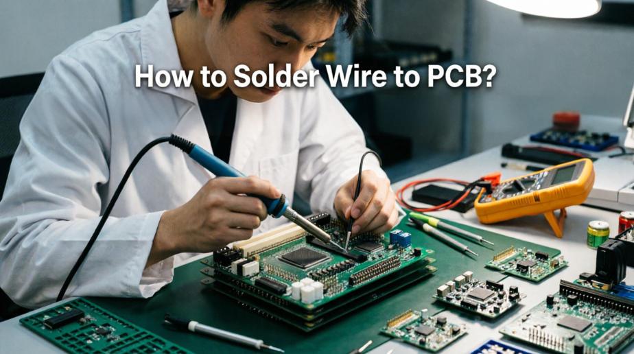
If you are searching for how to solder wire to pcb, this detailed practical guide walks you through standard procedures to create firm, reliable connections efficiently. Many beginners struggle with loose joints, cold solder and detached wires while learning how to solder wire to pcb. This guide covers tool preparation, standard workflows, error fixes, real industry use cases and practical skills for diverse circuit board application scenarios.
1. What Basic Tools Do You Need to Solder Wire to PCB?
Fully matched tools are essential for qualified wire soldering work. Unsuitable tools often damage circuit pads and internal circuitry. Below are all essential handheld tools and auxiliary materials for regular maintenance and assembly tasks.
1.1 Core Soldering Tools
- Temperature-controlled soldering iron: Adjustable heat output fits various wire gauges and pad dimensions.
- Solder wire: Lead-free solder is widely adopted for commercial electronic product assembly.
- Desoldering braid: Removes excess solder and corrects misaligned soldering positions easily.
1.2 Supporting Auxiliaries
Solder flux improves solder flow and effectively prevents cold solder joints.
A wire stripper removes outer insulation without scratching inner copper conductors.
2. What Is the Standard Step to Solder Wire to PCB?
Following a fixed operating sequence significantly boosts soldering success rates and connection durability. The full workflow is divided into four core stages: preprocessing, pre-tinning, joint soldering and final inspection.
2.1 Preprocess Wires and PCB Pads
Strip insulation to a proper length and twist stranded copper wires tightly together.
Clean oxide layers from PCB pads to ensure strong solder adhesion.
2.2 Pre-Tin Wire Ends and Empty Pads Separately
Apply a thin, even layer of solder to wire tips and target pads respectively.
Overly thick solder layers cause hidden dry joints and disrupt signal transmission.
2.3 Align Components and Complete Formal Soldering
Place pre-tinned wire ends onto designated pads and apply gentle heat with the iron.
Allow the joint to cool naturally once a smooth, uniform solder shape forms.
2.4 Trim Excess Material and Test Stability
Cut off redundant wire segments and wipe away residual flux from the board surface.
Lightly tug the wire to confirm no shifting or loosening occurs.
3. How to Solder Different Types of Wires to PCB Properly?
Stranded wires, solid-core wires and high-temperature cables require distinct soldering focuses. Targeted operating methods enhance connection stability across various working environments.
Different Wire Soldering Operation Comparison Table
| Wire Type | Key Operation Points | Applicable Working Scene |
| Stranded Multicore Wire | Fully twist strands before tinning to avoid loose copper filaments | General signal transmission and flexible internal wiring |
| Solid Single-Core Wire | Limit heating duration to prevent core softening and deformation | Fixed internal wiring inside equipment cabinets |
| High-Temperature Resistant Wire | Slightly raise iron temperature to ensure smooth solder melting | Internal wiring inside high-heat power circuits |
| Ultra-Fine Thin Wire | Use low-power soldering irons to avoid burning thin conductors | Precision wiring for compact miniature electronic modules |
4. How to Protect Tiny Fragile PCB Pads During Soldering?
Miniature pads on compact circuit boards easily peel off under prolonged heat exposure. Controlling heating duration and contact range remains the most effective way to safeguard vulnerable pads.
- Keep single heating sessions under 3 seconds to reduce substrate thermal expansion stress.
- Avoid holding the iron steadily on edge pads or pads with limited copper coverage.
- Apply appropriate flux to speed up solder fusion and shorten overall operating time.
5. What Common Mistakes Occur When You Solder Wire to PCB?
Most intermittent circuit faults stem from non-standard soldering habits. These summarized frequent errors help operators conduct self-checks and standardize daily operating routines.
5.1 Formation of Cold Solder Joints
Insufficient heat prevents full fusion between solder, copper wires and pads.
This defect leads to intermittent circuit disconnection under vibrating working conditions.
5.2 Excessive Solder Accumulation
Overapplied solder forms bulky bulges that easily trigger adjacent circuit short circuits.
It also increases overall board thickness and obstructs internal equipment assembly.
5.3 Improper Insulation Stripping Length
Excessively short exposed copper sections result in easy wire detachment after long-term tension.
Overly long exposed conductors raise potential short circuit risks greatly.
6. How to Repair Loose or Detached Wires on Finished PCB?
Aging wiring and poorly constructed solder joints gradually loosen during long-term service. Standard repair procedures restore stable connections without damaging the original circuit layout.
First clear away leftover old solder and thoroughly clean the surface of target pads.
Recondition wire ends and perform re-soldering following official standard workflows.
Apply fixing adhesive to wires installed in areas prone to continuous vibration.
7. Which Industrial Fields Demand Strict Wire-to-PCB Soldering Standards?
Different industries set varied reliability benchmarks for wire soldering quality. Referencing mature industry specifications helps technicians adopt the most suitable soldering techniques.
7.1 Automotive Electronics Industry
Internal vehicle control PCB units require vibration-resistant wire soldering solutions.
Strengthened solder joints steadily withstand frequent jolts and ambient temperature fluctuations.
7.2 Industrial Automation Industry
Signal wiring on industrial mainboards needs low-resistance and highly stable soldering performance.
It guarantees uninterrupted long-distance signal transmission inside factory workshops.
7.3 LED Lighting Industry
Power line soldering on lamp driver boards requires outstanding heat resistance capacity.
It prevents virtual joint failures caused by sustained heat emitted by lighting sources.
7.4 Medical Electronics Industry
Wiring connections on medical detection modules demand high safety and consistent stability.
Strict standardized soldering ensures reliable operation of high-precision diagnostic devices.
8. How to Set Suitable Soldering Iron Temperatures for PCB Wiring?
Proper temperature settings balance working efficiency and overall circuit board safety. Different substrate materials and wire specifications correspond to matched reasonable temperature ranges.
- Standard FR4 circuit boards: maintain stable working temperature between 320℃ and 360℃.
- Thin flexible circuit boards: lower temperature below 300℃ to prevent board deformation.
- High-current thick wire connections: moderately increase temperature to accelerate solder fusion speed.
9. What Practical Skills Boost Soldering Speed and Joint Quality?
Mastering practical operating skills shortens working duration while unifying solder joint appearance and structural stability. These methods work perfectly for batch wiring assembly tasks.
Complete unified pre-tinning on all prepared wires before starting formal wiring work.
Sort wires by specification in advance to avoid repeated adjustment of equipment parameters.
Keep soldering iron tips clean at all times to maintain stable thermal conductivity.
10. How to Reduce Signal Interference Caused by Improper Wire Soldering?
Unreasonable wiring layouts and irregular solder joints may introduce extra interference inside high-frequency circuits. Standardized soldering and routing rules effectively minimize such hidden electronic issues.
Separate soldering positions for power lines and signal lines to avoid crossed layout designs.
Control solder joint volume to lower adverse impacts from stray capacitance.
Arrange wires in identical directions for grouped signal connection lines.
11. FAQ: Frequently Asked Questions About Soldering Wire to PCB
This section collects common confusions encountered during daily wire soldering operations, delivering concise and field-verified solutions based on practical working experience.
11.1 Can I solder wires onto PCB without using flux?
You can finish simple temporary connections without flux, yet solder fluidity drops noticeably and cold solder joint risks rise sharply. Using appropriate flux always creates more durable and reliable electronic connections.
11.2 How do I fix lifted PCB pads after improper soldering?
Stop applying heat immediately once pads lift. Use fine insulated wires to bridge signals to nearby accessible through holes, and avoid reusing the damaged original pad for long-term stable use.
11.3 What is the ideal exposed copper length for regular wiring?
For common electronic wiring, keep exposed copper length between 3mm and 5mm. This range balances connection firmness and safety against accidental short circuits effectively.
11.4 Is hot glue necessary after finishing wire soldering?
It is not required for static internal wiring. Hot glue reinforcement is only recommended for wires installed inside mobile devices or vibration-prone equipment to enhance long-term stability.
11.5 Why do solder joints turn dark and dull after cooling?
Dull dark joints usually result from insufficient soldering temperature or oxidized solder materials. Replace fresh solder and raise operating temperature slightly to form bright, fully fused qualified joints.
12. Professional PCB Manufacturing and Wiring Support Services
After mastering complete wire-to-board soldering knowledge and standard skills, you can effectively complete daily maintenance, prototype assembly and on-site wiring tasks smoothly. Stable soldering workmanship greatly extends the overall service life of all finished electronic products.
Thindry supplies high-performance PCB and PCBA products covering automotive, industrial automation, LED lighting and medical electronic fields. We support on-demand customization and provide free DFM reports for every project to optimize structural design and simplify subsequent wiring and assembly work.
If you need customized circuit board prototypes, medium-batch production or professional assembly technical guidance, send your design documents and detailed demands to our professional engineering team via sales@pcbtry.com. We deliver reliable circuit solutions for global electronic developers and manufacturers.

0 Comments