



The practical inductor vs capacitor difference is the electrical quantity each component resists changing. A capacitor resists an abrupt change in voltage and stores energy in an electric field; an inductor resists an abrupt change in current and stores energy in a magnetic field. Their impedances also move in opposite directions as frequency rises, so they are complementary components rather than interchangeable substitutes.
Choose a capacitor when a circuit needs local charge, voltage smoothing, AC coupling, or a low-impedance path for unwanted high-frequency energy. Choose an inductor when the circuit must shape current, transfer energy in a switching converter, or place rising impedance in series with a noise path. Use both when a filter, resonant network, or converter needs simultaneous control of current and voltage.
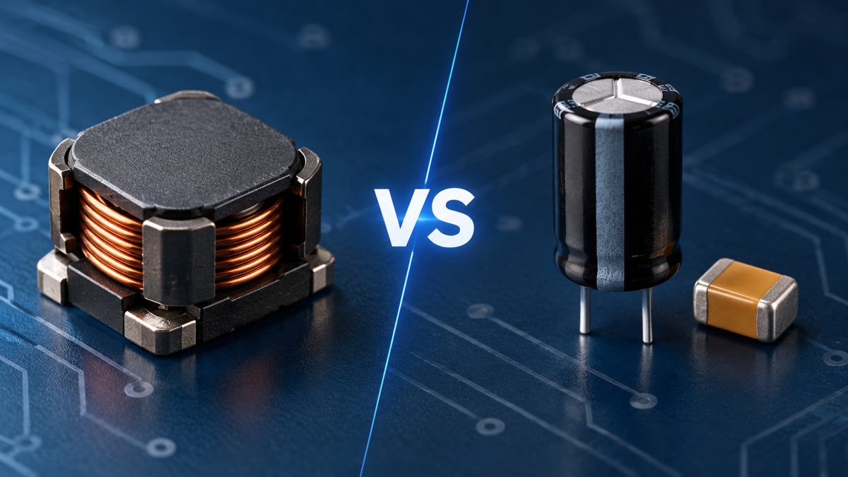
Inductor vs Capacitor Quick Comparison
An ideal inductor and capacitor are both reactive energy-storage components, but their voltage-current relationships, connection positions, and failure limits differ.
| Comparison Point | Inductor | Capacitor | Design Meaning |
| Stored field | Magnetic field | Electric field | Inductor energy depends on current; capacitor energy depends on voltage. |
| Cannot change instantly | Current | Voltage | Interrupting inductor current can create high voltage; forcing capacitor voltage to change demands current. |
| Ideal impedance | ZL = j2πfL | ZC = 1/(j2πfC) | Inductive impedance rises with frequency; capacitive impedance falls. |
| Ideal phase | Current lags voltage by 90° | Current leads voltage by 90° | The impedance phase is positive for L and negative for C. |
| Steady-state DC model | Short circuit after the transient | Open circuit after charging | This ideal model does not include winding resistance, leakage, or breakdown. |
| Common connection | Series with a current path | Across a rail or node; sometimes series for AC coupling | Connection follows whether the circuit must impede current or hold a node voltage. |
| Important real limits | DCR, saturation, core loss, Irms, SRF, temperature rise | ESR, ESL, DC bias, ripple current, leakage, voltage rating, SRF | Nominal L or C alone is not enough for selection. |
Core Specifications and What They Mean in a Real Circuit
Component selection starts with inductance or capacitance, but the usable result depends on current, voltage, frequency, temperature, construction, and parasitic elements.
| Parameter | Applies To | Practical Meaning | Verification Point |
| Inductance, L | Inductor | Sets current slope, ripple, reactance, and resonance with capacitance. | Check tolerance and the specified test frequency, current, and temperature. |
| Capacitance, C | Capacitor | Sets stored charge, transient support, reactance, coupling, and time constants. | Check effective capacitance at applied DC bias, temperature, and frequency. |
| DCR | Inductor | Produces I²R conduction loss and DC voltage drop. | Use the maximum value at the relevant temperature where available. |
| Isat | Inductor | Indicates the current at which core saturation causes inductance to fall by a stated amount. | Compare the manufacturer's drop criterion and curve, not only the headline current. |
| Irms | Inductor | Relates continuous current to a specified temperature rise. | Check ambient conditions, airflow, copper area, and the stated temperature-rise criterion. |
| ESR and ripple current | Capacitor | Control ripple heating and the immediate voltage step caused by pulsed current. | Use impedance and ESR data at the actual frequency and temperature. |
| ESL | Capacitor | Limits high-frequency bypass performance and makes the part inductive above resonance. | Include package, mounting, trace, and via inductance. |
| Voltage rating | Capacitor | Defines a dielectric stress boundary, not guaranteed effective capacitance. | Check derating, transients, polarity, and dielectric-specific bias behavior. |
| Self-resonant frequency, SRF | Both | Marks the frequency where intended reactance and parasitic reactance cancel. | Use the complete impedance curve around the intended operating band. |
| Tolerance and temperature behavior | Both | Determine the worst-case value available to the circuit. | Calculate with limits rather than nominal values alone. |
How Energy Storage and Transient Behavior Differ
A capacitor stores energy according to E = ½CV², whereas an inductor stores energy according to E = ½LI². These equations show why voltage stress dominates capacitor energy and current stress dominates inductor energy.
The differential relationships are equally important. For a capacitor, i = C(dv/dt); an instantaneous voltage step would require infinite current in the ideal model. For an inductor, v = L(di/dt); an instantaneous current step would require infinite voltage. Real resistance, source impedance, switching speed, clamping, and parasitics keep actual values finite, but the equations explain the common failure paths.
- Capacitor transient risk: high inrush current, excessive ripple heating, dielectric stress, or control-loop instability.
- Inductor transient risk: saturation during peak current, excessive temperature rise, or a high voltage spike when the current path is interrupted.
How Frequency Changes Inductive and Capacitive Impedance
For ideal sinusoidal operation, inductive reactance is XL = 2πfL, while capacitive reactance magnitude is XC = 1/(2πfC). Raising frequency therefore makes an ideal inductor harder to drive and an ideal capacitor easier to drive.
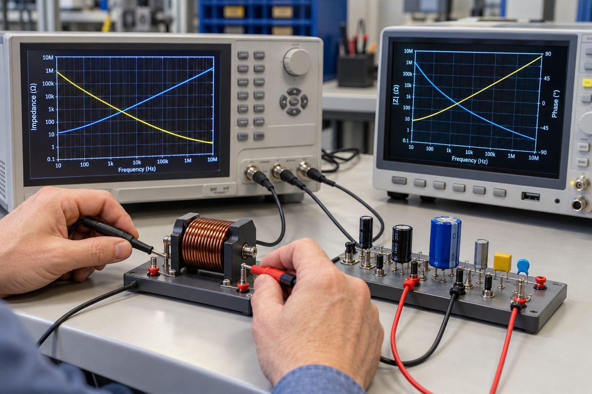
The familiar 90-degree phase relationships apply to ideal standalone reactances under sinusoidal steady-state conditions. In a real component, ESR, DCR, core loss, dielectric loss, and mounting parasitics add a resistive component and change the phase angle. Above self-resonance, an inductor can appear capacitive and a capacitor can appear inductive.
Two Calculation Examples for Comparing L and C
Reactance calculations provide a useful first estimate, provided the selected part still behaves as intended at the calculation frequency.
Example 1: Reactance at 100 kHz
For a 10 µH ideal inductor at 100 kHz:
XL = 2π × 100,000 × 10 × 10-6 = 6.28 Ω
For a 1 µF ideal capacitor at the same frequency:
XC = 1/(2π × 100,000 × 1 × 10-6) = 1.59 Ω
The result does not mean that the capacitor is “better.” It means the two parts present different impedances and normally occupy different positions in a circuit. The next check is the manufacturer's impedance curve under the actual bias, current, temperature, and mounting conditions.
Example 2: LC Resonant Frequency
For an ideal 10 µH inductor and 100 nF capacitor:
f0 = 1/(2π√LC) = approximately 159 kHz
This is only the ideal natural frequency. Source impedance, load impedance, component tolerance, Q, ESR, DCR, layout inductance, and damping determine the real peak, attenuation, and stability. A filter should therefore be simulated and measured in the actual circuit.
When to Choose a Capacitor
Choose a capacitor when the primary task is to control voltage at a node or provide a low-impedance path over a defined frequency range.
- Decoupling: supply fast local current near an IC and reduce rail disturbance.
- Bulk storage: support slower load steps and reduce low-frequency voltage droop.
- AC coupling: pass a changing signal while blocking the DC component between stages.
- Timing: create an RC time constant, subject to leakage, tolerance, and threshold accuracy.
- Snubbing: shape ringing or switching edges when selected with the surrounding resistance and parasitics.
Do not select from capacitance alone. A high-value ceramic capacitor may lose a significant part of its nominal capacitance under DC bias, and an electrolytic capacitor may have unsuitable ESR or ripple-current capability. Confirm the effective value and impedance at the intended operating point.
When to Choose an Inductor
Choose an inductor when the primary task is to control the rate of current change, transfer magnetic energy, or create series impedance without intentionally dissipating all unwanted energy as heat.
- Switching converters: set the current slope and transfer energy between switching states.
- Current-ripple control: reduce peak-to-peak ripple in a power path.
- Series filtering: impede unwanted AC current while allowing required DC current.
- RF choking: isolate an RF path from a bias supply below the inductor's useful self-resonant region.
- Resonance and matching: combine with capacitance to tune frequency response or transform impedance.
Check peak current against the saturation curve and RMS current against the thermal rating. DCR loss is approximately I2DCR for the DC component, while core and AC winding losses require frequency-dependent data. A nominal inductance value without these limits can lead to overheating or loss of current control.
When an LC Network Is the Better Choice
Use an LC network when a single reactive component cannot provide the required attenuation, energy transfer, or tuned response.
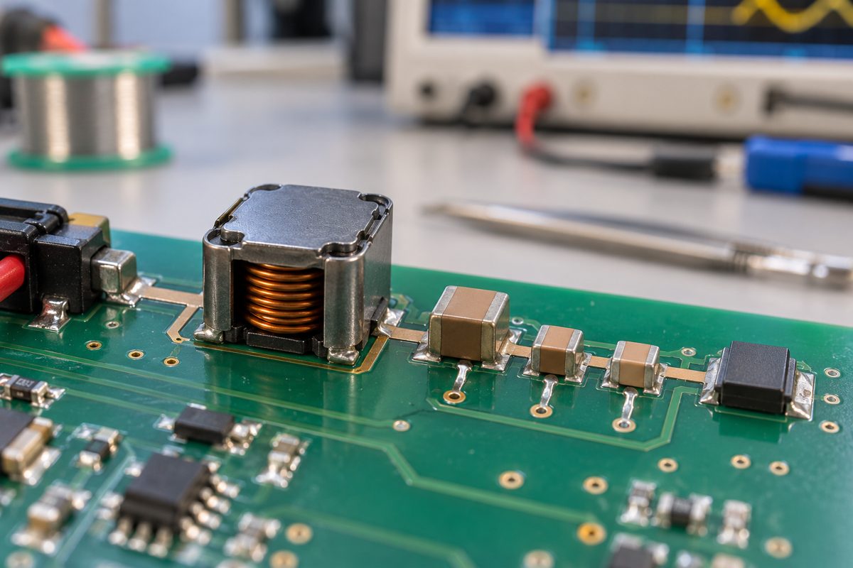
In a power filter, a series inductor can resist ripple current while a shunt capacitor provides a local return path and limits ripple voltage. In a switching converter, the inductor and capacitor perform separate functions and normally cannot replace one another. In RF circuits, L and C may form a tank or matching network whose behavior depends strongly on Q, tolerance, package, pads, vias, and nearby conductors.
LC filters can resonate and amplify rather than suppress a disturbance if source impedance, load impedance, and damping are ignored. Always check startup, load steps, control-loop stability, insertion loss, and component stress in addition to the calculated cutoff or resonant frequency.
Selection Rules for Real Inductors and Capacitors
The correct component is the one that meets the circuit function over worst-case operating conditions, not the one with the closest nominal value.
| Circuit Need | Starting Choice | Critical Checks | Common Mistake |
| Hold a supply node during a fast load step | Capacitor near the load | Effective capacitance, ESR, ESL, loop length, regulator stability | Adding remote bulk capacitance while ignoring local loop inductance |
| Limit converter ripple current | Power inductor | L at bias, Isat, Irms, DCR, core loss, temperature rise | Checking average current but not peak saturation current |
| Pass AC while blocking DC | Series capacitor | Lowest signal frequency, surrounding impedance, bias, distortion, startup transient | Choosing C without calculating the high-pass corner |
| Pass DC while impeding high-frequency noise | Series inductor or suitable ferrite bead | Impedance under DC bias, current rating, DCR, loss mechanism, SRF | Treating a lossy ferrite bead and an energy-storage inductor as identical |
| Create a tuned response | LC network | Q, tolerance, parasitics, damping, source and load impedance | Using only the ideal resonance equation |
| Suppress a switching spike | Application-specific RC, RCD, clamp, or magnetic solution | Energy, repetition rate, switch limits, waveform measurement, thermal stress | Adding a random capacitor or inductor without identifying the current path |
Common Design Errors and Their Root Causes
Most mistakes come from applying an ideal rule without checking the component's operating point or current path.
- “A capacitor passes all AC.” Real capacitor impedance reaches a minimum near self-resonance and then rises as ESL dominates.
- “An inductor is a short at DC.” Winding DCR creates voltage drop and heat, and DC bias may reduce inductance.
- “Higher capacitance is always better.” More capacitance can increase inrush, alter a control loop, enlarge discharge energy, or provide little high-frequency improvement when mounting inductance dominates.
- “Higher inductance is always better.” It can increase size, DCR, transient response time, cost, and saturation risk while lowering SRF.
- “Equal reactance means direct replacement.” Equal magnitude at one frequency does not match phase function, connection, energy domain, transient behavior, or limits.
- “The printed value is the in-circuit value.” Bias, current, temperature, frequency, tolerance, and aging can change the effective L or C.
Frequently Asked Questions
Can a capacitor replace an inductor?
Usually no. A capacitor cannot provide the controlled current ramp or magnetic energy transfer required from an inductor in a switching power stage. It may reduce voltage ripple in the same circuit, but that is a different function. A proposed substitution requires a complete circuit redesign rather than a value-for-value replacement.
Can an inductor replace a capacitor?
Usually no. An inductor cannot provide local charge at a supply node, block DC for AC coupling, or act as a shunt bypass capacitor. It can impede unwanted current in series with a line, but that does not perform the capacitor's voltage-support function.
Which component blocks DC?
An ideal capacitor blocks continuous steady-state DC after it charges, while an ideal inductor passes constant DC after the transient. Real capacitors have leakage, and real inductors have DCR and current limits, so neither ideal model is sufficient for final selection.
Which component is better for filtering noise?
Choose according to the noise path. A capacitor is useful when noise current should be returned from a node to a reference. An inductor or ferrite bead is useful when noise current should be impeded in series. An LC network can provide stronger filtering but may require damping.
Why does capacitor impedance fall with frequency?
For an ideal capacitor, XC = 1/(2πfC), so increasing frequency reduces reactance. A real capacitor stops following this trend near its self-resonant frequency because ESR and ESL become significant; above resonance it can appear inductive.
Why does inductor impedance rise with frequency?
For an ideal inductor, XL = 2πfL, so increasing frequency raises reactance. In a real inductor, core loss and winding capacitance modify the curve. At self-resonance the component no longer behaves as a simple inductor.
What is the phase difference between an inductor and capacitor?
In an ideal inductor, current lags voltage by 90 degrees. In an ideal capacitor, current leads voltage by 90 degrees. Real components have resistance and losses, so measured phase normally differs from exactly plus or minus 90 degrees.
Why are capacitors often connected in parallel and inductors in series?
A shunt capacitor can supply or absorb current locally while controlling node voltage. A series inductor directly carries and opposes changes in path current. These are common arrangements, not universal rules: AC-coupling capacitors are connected in series, and inductors can be used in parallel resonant networks.
What happens at LC resonance?
At ideal resonance, inductive and capacitive reactance magnitudes are equal. The resulting circuit behavior depends on whether L and C are connected in series or parallel and on the source, load, resistance, and Q. Real networks therefore need damping and measurement, not only an ideal formula.
What should be checked before ordering an inductor or capacitor?
Specify the complete part number, nominal value, tolerance, package, operating voltage or current, frequency, temperature range, relevant bias, ripple, pulse conditions, qualification needs, lifecycle status, and quantity. Compare manufacturer curves and test conditions rather than relying only on distributor summary fields.
Final Selection Checklist
Start with the variable that must be controlled: use capacitance for a voltage-node problem, inductance for a current-path problem, and an LC network when both functions are required. Then verify the decision using the real operating frequency, bias, peak and RMS stress, temperature, parasitics, source and load impedance, and transient conditions.
- Define the unwanted voltage or current waveform and its frequency range.
- Choose the component function before choosing a nominal value.
- Calculate ideal reactance or energy only as a starting point.
- Check manufacturer impedance, bias, saturation, loss, and thermal data.
- Evaluate component and layout parasitics in the actual circuit.
- Simulate where useful, then measure startup, steady state, transients, and temperature.
For questions about component requirements in an electronics project, contact PCBTRY at sales@pcbtry.com or use the PCBTRY contact page. Include the complete part number or target L/C value, operating voltage and current, frequency, package, temperature range, quantity, and any non-negotiable qualification requirements.
Technical References
The equations and selection boundaries in this guide were checked against publicly available technical material from Texas Instruments, Coilcraft's inductor education resources, Coilcraft's inductor selection guidance, and Murata's ceramic capacitor guidance. Always use the current manufacturer datasheet for a specific part number.
0 Comments